TEMES 1.0
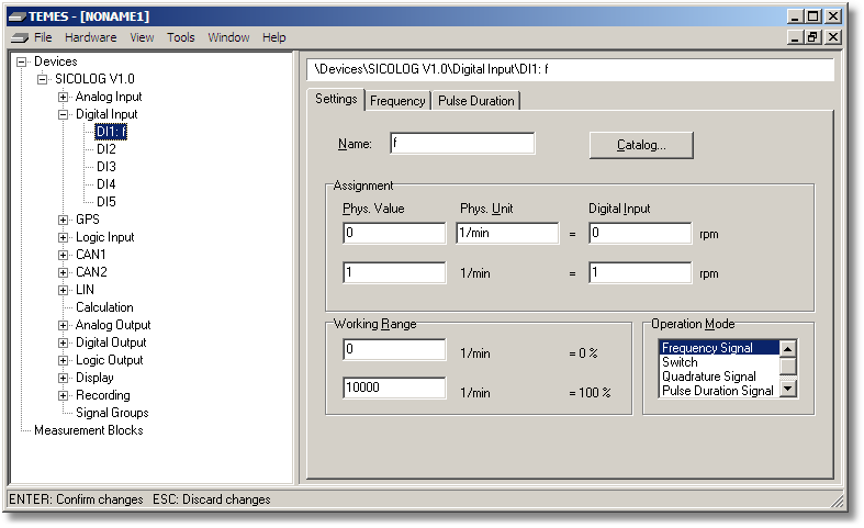
Figure 2-18: Parameter tree node Digital Input (Settings tab).
Name: Unique name of the input signal. If this field is empty, the corresponding input signal is deactivated.
Assignment: Definition of the linear relationship. See also Analog Input, Settings tab.
Working Range: Definition of the nominal physical signal range. These values will only be used as default values for chart axes, and as default values for output assignments.
Operation Mode: Definition of the operating mode.
Frequency Signal – The signal is a frequency signal. The frequency tab is used for further parameters.
Switch – The signal is a logical value yielding only 0 or 1.
Quadrature Signal – The signal is a quadrature signal (= phase counting mode signal). This kind of signals is only supported by the SICO2 family.
Pulse Duration Signal – The signal is the pulse width. The pulse duration tab is used for further parameters.
Counter – The signal is a 16-bit wrap-around counter which is incremented with each pulse.