TEMES 1.0
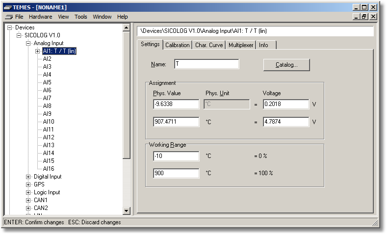
Figure 2-12: Parameter tree node Analog Input (Settings tab).
Name: Unique name of the input signal. If this field is empty the corresponding input signal is deactivated.
Catalog: Opens the catalog settings form.
Assignment: Definition of the linear relationship. The left side represents the physical signal p which depends on the measured signal m. The relationship is defined by two different physical signal values p0 = p(m0) and p1 = p(m1), and their corresponding measured signal values m0 and m1. Take care that p0 does not equal p1, and that m0 should not equal m1. Note that the values p0 and p1 are also used for the online calibration.
Factor = (p1 - p0) / (m1 - m0)
Offset = p0 - Factor ⋅ m0
Final Relationship:
p(m) = Factor ⋅ m + Offset
If Factor and Offset of the linear relationship are already known, the following values for m0, m1, p0 and p1 can be used:
m0 = 0
m1 = 1
p0 = Offset
p1 = Factor + Offset
The following image shows where the variables have to be put into the form. Note that the input fields for m0, m1, p0 and p1 allow floating point values only:
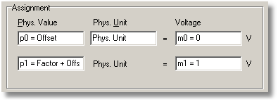
Figure 2-13: Assignment.
Physical Value: The first line defines p0, the second line defines p1.
Physical Unit: Unit of the physical signal p(m).
Voltage: The first line defines m0 in volts, the second line defines m1 in volts.
Working Range: Definition of the nominal physical signal range. These values will only be used as default values for chart axes, and as default values for output assignments.