TEMES 1.0
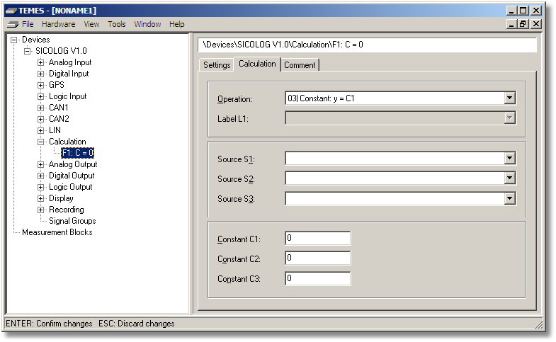
Figure 2-34: Parameter tree node Calculation (Calculation tab).
The Operation drop-down list selects the operation of the input signal (see below).
The Source S1 drop-down list represents source S1.
The Source S2 drop-down list represents source S2.
The Source S3 drop-down list represents source S3.
The Constant C1 edit box represents the constant C1.
The Constant C2 edit box represents the constant C2.
The Constant C3 edit box represents the constant C3.
The operations are defined as follows:
Op01 – External Function: (not yet supported)
Op02 – Char. Curve Lookup: (not yet supported)
Op03 – Constant: y = C1
Constant definition.
Op04 – Linear Transform: y = C1 ⋅ S1 + C2
Both constants may be floating point values. For SICO2 and DL16CAN: The constants are automatically adjusted for a calibration transformation if S1 is a voltage input signal.
Op05 – Sum: y = (S1 + S2) / ⌊C1⌋ with ⌊x⌋ = (int) x
Op06 – Difference: y = (⌊C1⌋ + S1 - S2) / ⌊C2⌋
Op07 – Product: y = (S1 ⋅ S2) / ⌊C1⌋
Op08 – Ratio: y = (S1 ⋅ ⌊C1⌋) / S2
Op09 – Equality: y = 1 if S1 = S2 else 0
Op10 – Less Than: y = 1 if S1 < S2 else 0
Op11 – Less Than or Equal To: y = 1 if S1 ≤ S2 else 0
Op12 – Condition: y = S2 if S1 ≠ 0 else S3
Op13 – Set constant conditionally: S2 = S3 if S1 ≠ C1
Op14 – And: y = S1 ∧ S2 (bitwise)
Op15 – Or: y = S1 ∨ S2 (bitwise)
Op16 – Exclusive Or: y = S1 ⊕ S2 (bitwise)
Op17 – Intel ↔ Motorola
Op18 – Mirror bits (lsb → msb, msb → lsb)
Op19 – Delay: y(k) = S1(k-1)
Op20 – Define counter
A counter is internally represented as 32-bit value. If the counter is directly accessed by its name, the lower 16-bit word of the counter is returned for the devices SICO2, DL16CAN and CFDL1.
Op21 – Increment counter: S1 = S1 + S2
Op22 – Decrement counter: S1 = S1 - S2
Op23 – Set counter conditionally: S2 = C2 if S1 ≠ C1
Op24 – Read counter: y = S1 / S2
Op25 – Set quadrature position conditionally: S2 = S3 if S1 ≠ C1
About calculated signals: All operations are performed with the quantized values of the corresponding input signal (= internal unsigned 16-bit representation of the physical signal for SICO2, DL16CAN and CFDL1. And signed 32-bit representation for the SICOLOG/SICO3/USBDL1 respectively). If operations on physical signals are required, then first a transform is needed from physical signal into bit domain. Then, the actual operation can be performed. And finally, the result can be transformed back from bit domain to physical domain. The transform between the two domains is done via a linear transform with the two constants factor and offset:
physical_value = factor ⋅ b + offset, where b is the corresponding bit value
Example 1: Two distances shall be added. The distance d1 and d2 are defined by
d1(b1) = factor1 ⋅ b1 + offset1, where b1 is the bit value of d1
d2(b2) = factor2 ⋅ b2 + offset2, where b2 is the bit value of d2
The addition of d1 and d2 yields
d1(b1) + d2(b2) = (factor1 ⋅ b1 + offset1) + (factor2 ⋅ b2 + offset2)
To simplify this equation we need to make the assumption that factor1 equals factor2. This assumption yields
d1(b1) + d2(b2) = factor1 ⋅ (b1 + b2) + (offset1 + offset2)
The final equation can be calculated with Op05 since b1 and b2 are in bit domain. The required steps can be summarized by:
1)Take care that both summands have the same factor. If not, use a linear transformation to adjust the factor of one of the summands.
2)Apply operation Op05 to add the bit representation of both summands.
3)The resulting bit value can be transformed back to physical domain by using the same factor as the summands and the sum of the summand's offset as result offset.
4)Get the physical assignment (p0, m0, p1 and m1) of the calculated signal from the result's factor and offset. (see also Assignment).
Example 2: Calculation of the power of the accelerated mass m (Constant moments of inertia of rotated masses can be taken into account by increasing the mass m correspondingly).
Work W is defined by
W(k) = ½ ⋅ m ⋅ v(k) ⋅ v(k), where v(k) is the speed signal in m/s²
Power P is defined by
P(k) = (W(k) - W(k-1)) / (t(k) - t(k-1))
The time period t(k) - t(k-1) is constant for every k, since all calculations are done with a constant loop rate of T. Combining all constants together yields:
P(k) = C ⋅ (v(k) ⋅ v(k) - v(k-1) ⋅ v(k-1)), with C = m / (2 ⋅ T)
Using bit values for v(k) instead of physical values yields:
P(k) = C ⋅ ((factor ⋅ b(k) + offset)² - (factor ⋅ b(k-1) + offset)²)
To simplify this equation we need to make the assumption that offset equals zero. This assumption yields:
P(k) = C ⋅ factor ⋅ factor ⋅ (b(k) ⋅ b(k) - b(k-1) ⋅ b(k-1))
We have to take into account that the result of the product b(k) ⋅ b(k) does not produce a 16-bit overflow. Therefore, we divide the product by the constant D (e. g. D = 65535). Finally, the equation reads:
P(k) = G ⋅ (b(k) ⋅ b(k) / D - b(k-1) ⋅ b(k-1) / D)
where G = C ⋅ factor ⋅ factor ⋅ D = (m ⋅ factor ⋅ factor ⋅ D) / (2 ⋅ T)
The final equation can be calculated with the following operations where the bit value of the speed is given by input signal v:
1)v² = Op07(S1 = v, S2 = v, C1 = D)
2)v(k-1)² = Op19(S1 = v²)
3)diff = Op06(S1 = v², S2 = v(k-1)², C1 = 0, C2 = 1)
4)P = Op04(S1 = diff, C1 = G, C2 = 0)